
Chapter 7 converts the converter-level decisions from Chapters 5 and 6 into physical winding turns and verifies the resulting magnetic flux. The primary turns must satisfy the maximum applied volt-seconds, the secondary and auxiliary turns must realize practical integer ratios, and the selected core must remain within both saturation and core-loss limits across the complete operating envelope.
← Previous Chapter
Next Chapter →
In This Chapter — Click to Expand
[INSERT RANK MATH TABLE OF CONTENTS HERE]
1. Primary Turns, Secondary Turns, and Flux Density Form One Iterative Design
A flyback transformer cannot be finalized by calculating primary turns, secondary turns, and flux density independently. The primary winding sets the magnetic flux excursion for the applied primary volt-seconds. The secondary winding determines the realized turns ratio and reflected voltage. The realized turns ratio changes duty cycle, demagnetization time, semiconductor stress, and current waveforms. Those changes can force the primary-turn calculation to be repeated.
The practical design therefore moves in a closed loop: select an initial primary-turn count, calculate the secondary and auxiliary turns, realize integer turns, recalculate the actual turns ratios, verify duty cycle and semiconductor stress, and finally confirm flux density and core loss at every important operating corner.
The design must also fit on a real bobbin. Additional turns may improve flux margin but increase copper length, winding layers, leakage inductance, parasitic capacitance, and window utilization. The correct turns count is therefore the lowest practical integer value that satisfies magnetic, electrical, thermal, insulation, and manufacturing constraints.
SOLIDMAG ENGINEERING INSIGHT
Turns Are Electrical, Magnetic, and Mechanical Variables
Primary and secondary turns do more than establish voltage conversion. They determine flux excursion, current transformation, winding length, layer count, gap requirements, leakage, capacitance, and manufacturing feasibility.
Whenever one winding turn count changes, the complete converter and transformer model should be updated rather than assuming the rest of the design remains unchanged.
2. Primary Turns from Applied Volt-Seconds
During the MOSFET ON interval, voltage is applied across the primary winding. Faraday’s law relates that applied volt-second product to the resulting change in core flux density.
Using the switching period and duty cycle:
Therefore:
Solving for the minimum primary turns required to remain within an allowable flux-density excursion:
| Variable | Meaning |
|---|---|
| NP,MIN | Minimum calculated primary turns |
| VP,ON | Voltage actually applied across the primary winding during the ON interval |
| D | Primary switch duty cycle |
| fs | Switching frequency |
| Ae | Effective magnetic core cross-sectional area |
| ΔBALLOW | Selected allowable flux-density excursion |
For a first-pass ideal calculation, the primary winding voltage may be approximated by the input bus. A refined calculation can account for MOSFET voltage drop, current-sense resistance, series wiring drop, and other elements that reduce the voltage actually appearing across the transformer primary.
DESIGN ASSUMPTION
Use the Voltage Across the Primary Winding
The turns equation is driven by the actual primary winding volt-seconds, not merely by a nominal source label. If the converter input is rectified mains, the magnetic design should use the actual DC bus conditions at the transformer, including low-line droop and control behavior.
3. Find the Maximum Primary Volt-Second Condition
The worst flux-density condition is the operating corner that produces the largest applied primary volt-seconds per switching cycle. It is not automatically minimum input voltage or maximum input voltage.
Important contributors include:
- Minimum and maximum input voltage
- Maximum duty-cycle limit
- Minimum switching frequency
- Frequency foldback or variable-frequency operation
- Startup and soft-start behavior
- Current-limit operation
- Burst or skip modes
- Controller propagation delays
- Input-bus ripple and hold-up behavior
For a regulated flyback converter, duty cycle normally changes with input voltage. A lower input voltage can therefore produce a larger duty cycle, while a higher input voltage applies more volts for a shorter time. The product must be evaluated rather than assuming one variable alone determines flux stress.
ENGINEERING CAUTION
Do Not Size Turns at Nominal Line Only
A transformer that is safe at nominal input voltage can exceed its intended flux limit at low line, minimum frequency, startup, current-limit, or another control corner. Evaluate the complete control envelope before accepting the primary turns.
4. Selecting the Practical Integer Primary Turns
The calculated minimum primary turns is rarely an exact integer. The first practical candidate is normally obtained by rounding upward:
However, the smallest integer above the theoretical minimum is not automatically the final answer. The chosen primary turns also determine whether practical integer secondary and auxiliary turns can realize the desired electrical ratios.
Increasing primary turns generally reduces flux excursion for the same applied volt-seconds:
But additional turns can also increase:
- Primary copper length and DCR
- Number of winding layers
- Window utilization
- Leakage inductance
- Interwinding capacitance
- Required magnetic reluctance for a fixed magnetizing inductance
- Manufacturing complexity
For a fixed target magnetizing inductance, additional primary turns generally require additional magnetic reluctance—usually through the intentional gap—to prevent the inductance from rising. Chapter 8 develops that relationship in detail.
SOLIDMAG ENGINEERING INSIGHT
Round the Calculation, Then Recalculate the Transformer
The correct primary turns are not obtained by rounding once and moving on. The selected integer value must be returned to the flux, gap, turns-ratio, winding, loss, and mechanical calculations.
A one-turn change can be insignificant in a hundred-turn winding and transformative in a five-turn winding. Integer turns are part of the engineering design, not a clerical detail.

Figure 7-1. Primary turns are selected so the maximum applied primary volt-seconds remain within the allowable flux-density excursion.
5. Secondary Turns from the Desired Turns Ratio
Using the primary-to-secondary turns-ratio convention established in Chapter 6:
the ideal secondary turns are:
If the design instead begins from a selected reflected voltage:
then:
The secondary winding must then be converted to a whole number of turns. The realized ratio is:
and the actual reflected voltage becomes:
That realized reflected voltage must be returned to the duty-cycle, demagnetization-time, MOSFET-stress, rectifier-stress, and current calculations.
| If Secondary Turns Are Rounded… | Typical Consequence |
|---|---|
| Down | Higher actual primary-to-secondary ratio and higher reflected voltage |
| Up | Lower actual primary-to-secondary ratio and lower reflected voltage |
| By a large percentage | Duty cycle, demagnetization time, and semiconductor stress can change materially |
| To only one or two turns | One-turn resolution can dominate the entire turns-ratio design |
6. Low-Voltage, High-Current Secondaries Need Special Attention
Low-voltage outputs often require only a few secondary turns. This makes integer-turn resolution particularly important. A calculated value of 1.4 turns cannot be implemented as 1.4 conventional turns on an ordinary bobbin.
Possible responses include:
- Increase primary turns so the desired ratio produces more secondary turns
- Adjust the reflected-voltage target
- Adjust the duty-cycle design
- Use a different core or winding window
- Revisit the output rectifier drop assumption
- Use planar or fractional-turn techniques only when the physical construction genuinely supports them
Higher secondary current can also make conductor selection and termination geometry more important than the turns count itself. A five-turn secondary may require substantially more copper area than a much longer primary winding.
ENGINEERING CAUTION
A Fractional Electrical Turn Is Not Automatically a Manufacturable Turn
Do not leave fractional turns in the design output unless the chosen construction intentionally supports a fractional-turn implementation. Conventional bobbin-wound transformers require integer physical turns.
7. Auxiliary and Multiple-Output Turns
An auxiliary winding is commonly used to power the primary-side controller or to provide another isolated output. A first estimate relative to the main secondary is:
| Variable | Meaning |
|---|---|
| NA | Auxiliary turns |
| VA | Desired auxiliary output voltage |
| VD,A | Auxiliary rectifier forward drop |
| NS | Main secondary turns |
| VO | Main regulated output voltage |
| VD | Main secondary rectifier forward drop |
This is only a starting point. Auxiliary and additional outputs are affected by leakage inductance, winding resistance, diode drop, winding placement, load distribution, and cross-regulation.
After integer auxiliary turns are selected, calculate the expected idealized winding voltage from the realized turns ratio:
Then verify the actual auxiliary voltage in the complete converter across line, load, startup, burst, and transient conditions.
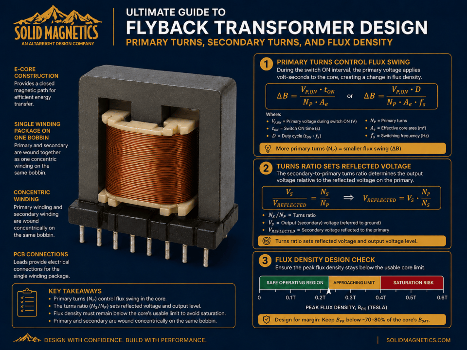
Figure 7-2. Theoretical turns ratios must be converted to integer physical turns and then returned to the converter calculations.
8. Flux Density from Magnetizing Current
The same flux excursion calculated from applied volt-seconds can also be expressed from magnetizing inductance and current change:
For DCM or BCM operation where the magnetizing current begins at approximately zero:
For CCM:
The current-based and volt-second-based calculations should agree when they describe the same switching interval and use consistent assumptions. A disagreement is a useful diagnostic that the design has mixed operating points, duty cycles, inductance values, or voltage definitions.
SOLIDMAG ENGINEERING INSIGHT
Use Two Independent Flux Checks
Checking flux from both applied volt-seconds and magnetizing-current change provides a valuable consistency test. Both methods describe the same magnetic excursion from different sides of the converter.
If they do not agree, resolve the discrepancy before proceeding to gap, core-loss, or winding design.
9. Peak Flux Density in DCM, BCM, and CCM
Flux excursion and absolute peak flux density are not always the same quantity. In DCM and BCM, the magnetizing current returns to approximately zero, so the incremental flux associated with that current returns toward its starting point before the next cycle.
For a first-order DCM or BCM estimate:
In a simplified incremental analysis, the starting point is often taken as the cycle reference. Real ferrite still exhibits remanence and hysteresis, so absolute magnetic flux should not be described as literally becoming zero.
In CCM, the minimum current is nonzero. A useful current-based representation is:
The flux excursion is:
while the absolute peak flux condition depends on the magnetic operating reference, remanence, material behavior, and current bias.
ENGINEERING CAUTION
CCM Ripple Is Not the Same as CCM Peak Flux
A design can have modest ripple flux while carrying substantial residual magnetizing current. Saturation margin must consider the absolute magnetic bias condition as well as the AC flux excursion.
10. Saturation Margin and Temperature
Ferrite saturation flux density generally decreases as temperature increases. The magnetic design should therefore compare the worst-case peak flux against a temperature-appropriate limit, not only a room-temperature datasheet value.
The selected design limit should include margin for:
- Core material variation
- Effective core-area tolerance
- Primary-turn tolerance
- Magnetizing-inductance tolerance
- Gap tolerance
- Current-limit tolerance
- Input-voltage variation
- Switching-frequency variation
- Startup and transient conditions
- Maximum expected core temperature
Hard saturation is not the only magnetic constraint. Core loss can force a substantially lower usable flux excursion than the saturation limit, particularly at higher switching frequencies.
Therefore, the accepted design must satisfy both saturation margin and core-loss/thermal limits.
| Check | What It Protects Against |
|---|---|
| Peak flux vs. temperature-adjusted saturation limit | Inductance collapse and current runaway |
| Flux excursion vs. material loss data | Excessive ferrite heating |
| Current limit vs. minimum inductance | Unexpected peak current |
| Turns and effective area tolerance | Loss of magnetic margin in production |
11. Worked Example — Converting the Chapter 6 Ratio into Integer Turns
DESIGN ASSUMPTION
Educational Continuation of the Chapter 5–6 Design
This example continues the provisional design developed in Chapters 5 and 6. It is intended to show the turns-and-flux iteration, not to finalize a production core or transformer.
| Parameter | Value |
|---|---|
| Primary ON voltage at low line | 100 V |
| Duty cycle at low line | 0.45 |
| Switching frequency | 100 kHz |
| Magnetizing inductance | 147.3 µH |
| Peak primary current | 3.06 A |
| Selected turns ratio target | Approximately 8:1 |
| Output voltage | 12 V |
| Main rectifier drop | 0.6 V |
| Candidate effective core area | 80 mm² |
| Initial allowable flux excursion | 0.18 T |
Step 1 — Calculate the Minimum Primary Turns
The theoretical minimum is therefore 31.25 turns. Round upward to the first candidate:
Step 2 — Calculate the Ideal Secondary Turns
This is already an exact integer solution:
Step 3 — Calculate the Realized Reflected Voltage
The realized reflected voltage remains essentially equal to the Chapter 6 target.
Step 4 — Verify Flux Excursion from Volt-Seconds
Step 5 — Verify Flux Excursion from Current
The two independent flux calculations agree closely, confirming that the selected electrical and magnetic assumptions are internally consistent.
Step 6 — Calculate a Provisional Auxiliary Turns Count
The physical winding must use an integer number of turns. Two turns is the first practical candidate.
The idealized auxiliary voltage corresponding to two turns is:
That result illustrates why an auxiliary winding cannot be finalized from a ratio alone. Winding placement, diode drop, controller operating current, cross-regulation, and real converter behavior must be verified.
| First-Pass Quantity | Result |
|---|---|
| Minimum calculated primary turns | 31.25 |
| Selected primary turns | 32 |
| Selected secondary turns | 4 |
| Realized turns ratio | 8:1 |
| Actual reflected voltage | 100.8 V |
| Flux excursion from volt-seconds | 0.176 T |
| Flux excursion from current | 0.176 T |
| Provisional auxiliary turns | 2 |
| Idealized 2-turn auxiliary voltage | 5.8 V |
SOLIDMAG ENGINEERING INSIGHT
The Integer-Turn Solution Closed Cleanly—but the Core Is Not Yet Final
The 32-turn primary and 4-turn secondary reproduce the desired reflected voltage and produce consistent flux calculations for the provisional 80 mm² core area.
Chapter 8 must now determine whether a real core, gap, and A_L value can realize 147.3 µH with 32 turns while satisfying energy storage, fringing, tolerance, winding fit, core loss, and manufacturability.
12. Production Tolerances and Verification
The nominal turns count is usually exact, but the magnetic conditions it produces are not. Production verification must account for variation in core area, material, gap, inductance, current limit, frequency, and temperature.
Useful worst-case checks include:
- Maximum applied primary volt-seconds with minimum effective core area
- Minimum magnetizing inductance with maximum current-limit threshold
- Maximum core temperature with reduced saturation flux density
- Minimum switching frequency at maximum duty cycle
- Actual integer turns and realized turns ratio
- Auxiliary winding regulation across line and load
- Winding resistance and temperature rise
- Gap and A_L tolerance after assembly
The completed transformer should be measured for magnetizing inductance, leakage inductance, DCR, turns, polarity, and dielectric integrity. Converter testing should then confirm current, voltage stress, temperature, regulation, and EMI.
ENGINEERING CAUTION
Do Not Treat the Integer Turns as the End of Magnetic Design
The turns calculation determines the winding ratios and flux excursion, but the selected turns are only useful if a real core and gap can produce the target magnetizing inductance with acceptable loss, temperature, fringing, insulation, and manufacturing tolerance.
13. Design Handoff to Flyback Air-Gap Design
At the end of Chapter 7, the design should have a coherent set of integer winding turns and a verified flux-density excursion. The next step is to create the magnetic reluctance required to realize the target magnetizing inductance and stored energy.
Chapter 8 will use:
- Selected primary turns
- Target magnetizing inductance
- Core effective area
- Peak primary current
- Stored energy
- Desired A_L value
- Flux-density margin
- Core and gap tolerances
to determine the required air gap and evaluate gap construction, fringing fields, winding placement, factory-gapped cores, distributed gaps, tolerance, and verification.
SOLIDMAG ENGINEERING INSIGHT
Primary Turns and Air Gap Must Be Designed Together
Primary turns establish the magnetic flux produced by the electrical waveform. The air gap establishes much of the magnetic reluctance that allows those turns to produce the required magnetizing inductance and energy-storage capability.
Changing the primary turns changes the required gap. Changing the gap changes inductance and current. The two variables must therefore be closed together rather than designed in isolation.
Technical References for This Chapter
For detailed core geometry, effective area, AL, and magnetic-material data, use the manufacturer datasheet for the selected core set and material. The equations in this chapter are first-pass magnetic design relationships and should be verified with actual component data and prototype measurements.
Related SolidMagnetics Resources
Ready to Design a Flyback Transformer?
Move from design theory to an automated magnetic design. Enter the converter requirements and evaluate a coordinated transformer candidate, winding geometry, loss estimates, thermal performance, and CAD output.
← Previous Chapter
Next Chapter →
