
Chapter 15 brings the entire Ultimate Guide to Flyback Transformer Design into one practical engineering workflow. The goal is not to repeat every equation from the previous chapters, but to show how requirements, operating mode, energy storage, turns ratio, flux, gap, core, conductors, winding arrangement, parasitics, loss, thermal behavior, manufacturing limits, and validation must converge together. It also explains which parts of that workflow are well suited to automation and which still require engineering judgment.
← Previous Chapter
Guide Home →
In This Chapter — Click to Expand
Table of Contents
1. The Complete Flyback Transformer Design Loop
A practical flyback transformer design is an iterative loop rather than a one-way sequence. The output of one calculation frequently changes the assumptions used by another.
- Define electrical, control, isolation, thermal, mechanical, and manufacturing requirements.
- Choose or verify conduction-mode strategy.
- Determine energy per cycle, magnetizing inductance, and current levels.
- Select turns ratio and reflected voltage.
- Choose integer primary, secondary, and auxiliary turns.
- Check flux density and saturation margin.
- Select a core geometry, ferrite material, and gap/AL combination.
- Select conductors and calculate winding fit.
- Create the winding and insulation stack.
- Estimate leakage inductance and interwinding capacitance.
- Calculate copper loss, core loss, and temperature rise.
- Generate manufacturing limits and validation tests.
- Repeat until every hard constraint passes and the preferred design objective is optimized.
SOLIDMAG ENGINEERING INSIGHT
The Best Design Is the Best Converged System
A transformer candidate is not good because one equation looks favorable. It is good when electrical stress, magnetic margin, winding fit, insulation, parasitics, loss, temperature, manufacturability, and cost all remain acceptable together.
That system-level convergence is the central idea behind both manual and automated flyback transformer design.
2. Practical Example A — 85–265 VAC to 12 V / 5 A
WORKED DESIGN EXAMPLE
Example A Requirements
This example summarizes the design thread developed through Chapters 4–14. It begins with a universal-input isolated flyback supplying a 12 V / 5 A main output and a small auxiliary output.
The values below are educational design assumptions, not a released production transformer.
| Requirement | Example Value |
|---|---|
| AC input | 85–265 VAC |
| Representative primary-bus design range | Approximately 100–375 VDC for the educational calculations |
| Main output | 12 V / 5 A |
| Auxiliary output | 5 V / 0.1 A |
| Total output power | 60.5 W |
| Efficiency assumption | 88% |
| Switching frequency | 100 kHz |
| Low-line duty-cycle assumption | 0.45 |
| Isolation | To be defined from applicable end-product safety standard |
Estimated input power is:
The corresponding energy processed per 100 kHz cycle is:
These two numbers establish the scale of the magnetic-energy problem before any core or wire is selected.
3. Example A — Energy, Magnetizing Inductance, and Peak Current
Using the educational low-line operating point from Chapter 5, a current-starts-near-zero candidate produced:
| Quantity | Example Result |
|---|---|
| Magnetizing inductance | 147.3 µH |
| Peak primary current | 3.06 A |
| Primary RMS current | 1.18 A |
| Peak stored energy | Approximately 690 µJ |
The important point is not the exact number; it is the coupling among energy, inductance, and current. Changing magnetizing inductance changes the current ramp, operating mode, copper requirement, current-limit margin, gap requirement, and thermal result.
ENGINEERING CAUTION
Do Not Freeze Magnetizing Inductance Before Checking the Complete Operating Envelope
A magnetizing inductance that looks attractive at one line/load point may force undesirable DCM/CCM behavior, peak current, demagnetization time, or current-limit margin elsewhere.
4. Example A — Turns Ratio, Integer Turns, and Flux
Chapter 6 selected a reflected-voltage target near 100 V. With a 12 V output and approximately 0.6 V rectifier drop, the ideal primary-to-secondary turns ratio was close to 8:1.
Using a provisional effective core area of 80 mm² and an allowable first-pass flux excursion of 0.18 T, Chapter 7 produced:
| Quantity | Example Result |
|---|---|
| Calculated minimum primary turns | 31.25 |
| Selected primary turns | 32 |
| Selected secondary turns | 4 |
| Realized turns ratio | 8:1 |
| Actual reflected voltage | 100.8 V |
| Flux excursion from volt-seconds | 0.176 T |
| Flux excursion from current | 0.176 T |
SOLIDMAG ENGINEERING INSIGHT
Independent Flux Calculations Should Agree
The volt-second and current-based flux calculations describe the same magnetic excursion from different sides of the design.
Agreement between them is a powerful automated consistency check; disagreement often reveals mixed assumptions, wrong units, or inconsistent operating points.
5. Example A — Gap, Core, and Material Candidate
With 32 primary turns and 147.3 µH target magnetizing inductance, Chapter 8 obtained a target inductance factor:
and a first-pass gap-dominated effective gap estimate near:
Chapter 9 then compared core candidates rather than assuming the provisional 80 mm² geometry was final.
| Candidate | Ae | Aw | MLT | Example Flux | Initial Observation |
|---|---|---|---|---|---|
| EE | 75 mm² | 110 mm² | 58 mm | 0.188 T | Flexible, but lowest flux margin |
| ETD | 90 mm² | 125 mm² | 52 mm | 0.156 T | Strong window and flux margin |
| PQ | 85 mm² | 100 mm² | 47 mm | 0.165 T | Compact with shortest turn length |
The ETD candidate ranked well in the educational comparison, but a production choice would still require actual manufacturer geometry, material loss curves, bobbin, gap availability, sourcing, and mechanical constraints.
6. Example A — Conductors and Winding Construction
Chapter 10 converted the current waveforms into first-pass conductor areas using an illustrative 4 A/mm² screening current density.
| Winding | RMS Current | First-Pass Copper Area |
|---|---|---|
| Primary | 1.18 A | 0.295 mm² |
| Secondary | 9.44 A | 2.36 mm² |
The high-current secondary requires much more copper area despite having only four turns. Chapter 11 then placed the conductors in an illustrative split-primary stack:
| Radial Position | Illustrative Stack |
|---|---|
| Innermost | 16-turn primary section |
| Next | Primary-secondary insulation barrier |
| Next | 4-turn high-current secondary |
| Next | Primary-secondary insulation barrier |
| Outermost | 16-turn primary section |
That winding arrangement improves magnetic coupling relative to a simple primary-secondary stack but also increases primary-secondary interface area and can therefore raise interwinding capacitance.
A practical flyback transformer design is an iterative engineering process in which electrical, magnetic, mechanical, thermal, insulation, parasitic, and manufacturing requirements must converge. Each design stage produces constraints and inputs for the stages that follow.
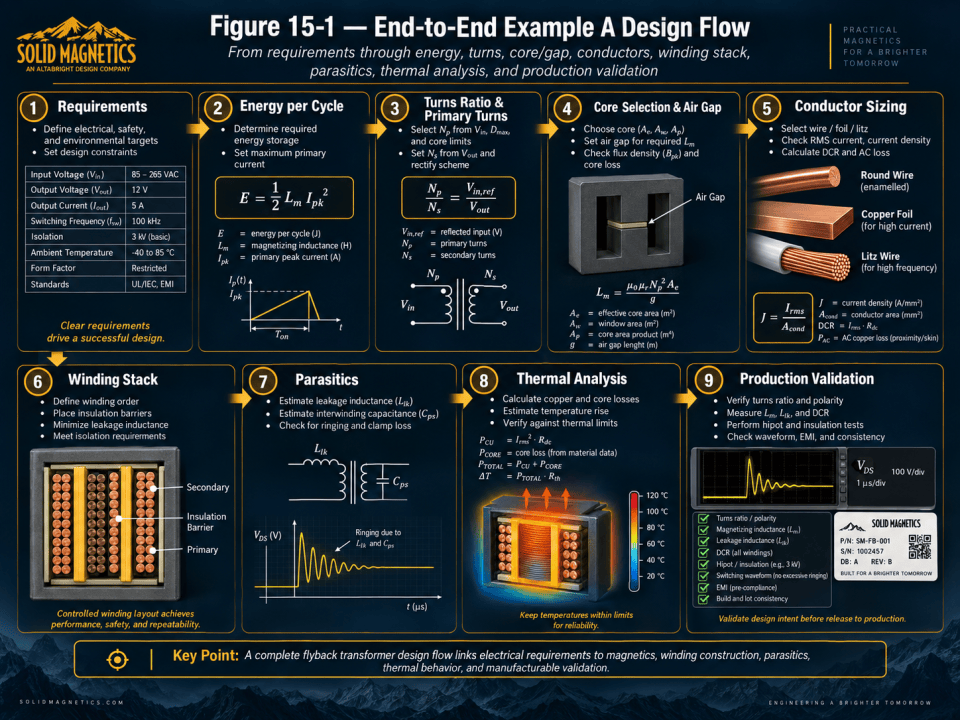
The complete workflow links the original product requirements to energy storage, magnetizing inductance, turns ratio, integer turns, core and gap selection, conductor sizing, winding construction, parasitic behavior, thermal performance, and production controls. This traceable sequence is also the foundation for automating repetitive flyback transformer design calculations while preserving engineering review and validation.
Figure 15-1. End-to-end Example A design flow from requirements through energy, turns, core/gap, conductors, winding stack, parasitics, thermal analysis, and production validation.
7. Example A — Parasitics, Loss, and Temperature
Chapter 12 used illustrative parasitics of 1.5 µH primary-referred leakage inductance and 40 pF primary-secondary capacitance. At 3.06 A peak primary current, leakage energy was:
A fully dissipative 100 kHz clamp would therefore see a first-order leakage-energy loss near:
Chapter 13 then combined temperature-corrected copper loss, AC winding factors, and illustrative ferrite loss into a transformer loss budget:
| Loss Component | Example Result |
|---|---|
| Primary winding loss | 0.240 W |
| Secondary winding loss | 0.285 W |
| Auxiliary / lead allowance | 0.050 W |
| Core loss | 0.599 W |
| Total transformer loss | 1.174 W |
| Illustrative temperature rise | 37.6°C |
| Illustrative temperature at 50°C ambient | 87.6°C |
Because resistance and ferrite loss are temperature dependent, the calculation must be iterated. The example temperature is therefore a convergence point to be refined, not a one-pass guarantee.
8. Example A — Manufacturing and Validation Handoff
Chapter 14 converted the nominal design into measurable production controls.
| Design Variable | Production / Validation Control |
|---|---|
| 32:4 turns | Turns-ratio and polarity test |
| 147.3 µH nominal Lm | Defined inductance range and test conditions |
| Leakage target | Short-circuit leakage test |
| Primary / secondary DCR | Temperature-referenced resistance limits |
| Isolation construction | Released insulation system and dielectric test plan |
| Winding arrangement | Drawing, winding specification, in-process inspection |
| Parasitic behavior | Qualification and converter-level validation |
| Thermal prediction | Prototype temperature verification |
SOLIDMAG ENGINEERING INSIGHT
The Worked Example Is a Traceable Chain
Each production control exists because an upstream equation or design constraint depends on it.
This traceability is what turns a transformer calculation into a professional engineering design package.
9. Practical Example B — A Lower-Voltage 48 V Input Flyback
WORKED DESIGN EXAMPLE
Example B — A Different Design Problem
A second example shows why flyback design cannot be reduced to one fixed set of transformer proportions.
Assume a 36–60 VDC input, isolated 12 V / 2 A output, 100 kHz nominal switching frequency, and 90% efficiency target.
| Requirement | Example B |
|---|---|
| Input | 36–60 VDC |
| Output | 12 V / 2 A |
| Output power | 24 W |
| Efficiency assumption | 90% |
| Input power | 26.7 W |
| Switching frequency | 100 kHz |
Compared with Example A, the energy per cycle is less than half. The input voltage is also much lower, so reflected-voltage, turns-ratio, MOSFET-stress, and winding-current tradeoffs shift substantially.
At the same switching frequency, Example B can often use fewer primary turns for the same core area and flux limit because the applied primary volt-seconds are lower. But primary RMS current can become more significant because the power is delivered from a lower input voltage.
| Design Dimension | Example A | Example B — Expected Direction |
|---|---|---|
| Energy per cycle | 687.5 µJ | 267 µJ |
| Primary voltage | High-voltage rectified mains | 36–60 VDC |
| Primary current | Moderate | Potentially higher relative to power |
| Isolation challenge | Universal-mains safety | Application dependent |
| MOSFET voltage stress | High | Lower |
| Primary turns tendency | Higher | Potentially lower |
| Copper emphasis | Secondary heavy-current | Primary current can become more important |
| Core size pressure | Higher power / energy | Lower total power |
SOLIDMAG ENGINEERING INSIGHT
Automation Must Rebuild the Design from the Requirements
Example B should not be produced by scaling Example A linearly. Different input voltage, power, current, isolation, and semiconductor constraints change the preferred turns ratio, core, gap, conductor, and winding arrangement.
A robust automated designer regenerates and reranks candidates rather than scaling a previous transformer.
10. Candidate Generation Is Better Than One-Shot Sizing
A manual designer often develops several plausible transformer candidates and rejects them as new constraints appear. Automation should formalize the same behavior.
For each combination of core, material, turns, gap, conductor, and winding arrangement, the software can calculate a candidate record containing:
- Electrical operating points
- Conduction mode at each line/load corner
- Magnetizing inductance
- Peak, average, and RMS currents
- Turns ratio and reflected voltage
- Integer turns
- Flux density and saturation margin
- AL and gap requirement
- Core-loss estimate
- Conductor selection and layer geometry
- Window utilization
- Leakage/capacitance estimate or target
- Copper loss and thermal estimate
- Mechanical dimensions
- Safety / insulation feasibility
- Manufacturing notes
- Pass/fail reasons
Candidates that violate hard constraints should be rejected before optimization scoring.
11. Separate Hard Constraints from Optimization Objectives
Automated design becomes much more reliable when feasibility and preference are separated.
### Hard Constraints
- Saturation margin
- Maximum semiconductor voltage/current
- Required inductance range
- Winding fits in the window
- Required creepage/clearance and insulation construction
- Maximum temperature
- Mechanical envelope
- Manufacturable integer turns
- Available core/material/gap combination
A candidate that violates a hard constraint should not receive a good score because it is small or inexpensive. It should be marked infeasible.
Optimization Objectives
- Smaller size
- Higher efficiency
- Lower material cost
- Lower temperature rise
- Lower EMI risk
- Lower leakage
- Lower capacitance
- Simpler manufacturing
- Greater design margin
A weighted optimization score can then rank only the feasible candidates:
where wi represents user-selected priority and si is a normalized candidate metric.
ENGINEERING CAUTION
Do Not Let Optimization Weights Override Physics
A user preference for minimum size must not be allowed to accept a saturated core, unsafe insulation system, excessive semiconductor stress, or unmanufacturable winding.
Optimization weights should rank feasible designs; they should not redefine feasibility.
12. Automated Operating-Corner Analysis
One of the highest-value automation tasks is generating and checking operating corners consistently.
| Dimension | Examples of Corners |
|---|---|
| Input | Minimum, nominal, maximum |
| Load | No load, light load, nominal, full load, overload |
| Frequency | Minimum, nominal, maximum, foldback regions |
| Inductance | Minimum, nominal, maximum |
| Current limit | Minimum / maximum threshold |
| Temperature | Cold, nominal, hot |
| Material | Nominal and worst relevant tolerance |
| Operating mode | DCM, BCM, CCM transitions where applicable |
The software can calculate all combinations or use a more efficient corner-generation strategy, then record the worst condition for each constraint.
SOLIDMAG ENGINEERING INSIGHT
Automation Is Excellent at Repetition and Bookkeeping
Engineers are good at understanding unusual behavior; computers are good at checking hundreds or thousands of combinations without forgetting one.
Operating-corner enumeration is therefore one of the strongest reasons to automate transformer design.
13. Automated Core and Material Database Search
A core database allows the design engine to search across actual geometries and materials rather than relying on generic core families.
Useful database fields include:
- Manufacturer
- Core family and part number
- Material grade
- Ae, AMIN, Aw, le, Ve
- Mean turn length
- Bobbin dimensions
- Available AL or gap options
- Core-loss data or model coefficients
- Temperature-dependent saturation data
- Mechanical dimensions
- Cost and sourcing metadata
- Approved usage range
The software can first reject cores that fail magnetic area, window area, mechanical size, or gap feasibility, then perform more expensive winding and thermal calculations on the remaining candidates.
Automated flyback transformer design is most effective when the software generates and evaluates multiple candidate designs rather than producing a single one-shot result. Each candidate can be evaluated across operating corners, magnetic limits, winding fit, insulation requirements, thermal behavior, and manufacturing constraints.
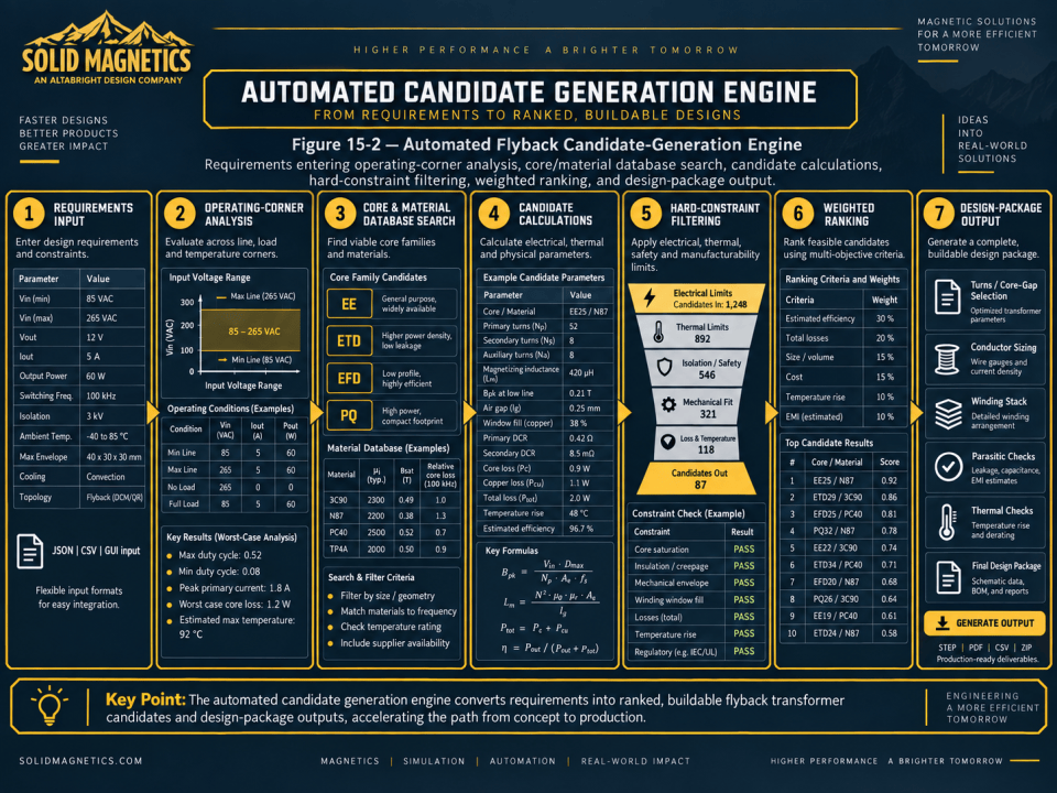
The candidate-generation engine first eliminates designs that violate mandatory electrical, magnetic, thermal, mechanical, or safety constraints. The remaining feasible candidates can then be ranked according to user priorities such as efficiency, size, temperature rise, cost, EMI risk, and manufacturability before the selected design is converted into engineering and manufacturing outputs.
Figure 15-2. Automated flyback candidate-generation engine showing requirements entering operating-corner analysis, core/material database search, candidate calculations, hard-constraint filtering, weighted ranking, and design-package output.
14. Automated Winding Geometry and CAD-Ready Parameters
Once a feasible electrical candidate exists, automation can translate it into geometric variables required by a CAD template or manufacturing drawing.
- Bobbin clearance
- Winding width
- Primary and secondary radial positions
- Turns per layer
- Layer count
- Conductor diameter or foil thickness
- Layer pitch
- Insulation thickness
- Margins
- Winding pack height and width
- Lead and pin assignments
- Core dimensions and gap representation
A CAD automation layer should use typed, validated geometry from the engineering model rather than recalculate transformer physics inside the CAD worker.
SOLIDMAG ENGINEERING INSIGHT
Separate Engineering Calculations from CAD Automation
The calculation engine should decide what the transformer is. The CAD system should build that approved geometry.
Keeping those responsibilities separate improves traceability, testing, debugging, and future support for additional core or winding technologies.
15. Automated Design Package Outputs
A useful automated workflow can generate more than a single numeric answer. A complete design package can include:
- Design summary
- Input assumptions and requirements
- Selected and alternate candidates
- Electrical calculations
- Magnetic calculations
- Winding schedule
- Core and material selection
- Air-gap or AL target
- Loss and thermal estimates
- Tolerance and worst-case checks
- Manufacturing notes
- Production test limits
- BOM
- 2D manufacturing drawing
- 3D CAD model
- STEP or neutral CAD export
- Machine-readable result data
Not every automated system will implement every output at once, but this is the logical end state of a traceable magnetic-design platform.
ENGINEERING CAUTION
Automation Output Is Not Certification
An automated report can document design assumptions and calculations, but it does not replace safety certification, prototype validation, regulatory testing, or engineering sign-off for a production product.
16. Where Engineering Judgment Still Matters
Some decisions remain difficult to automate completely because they depend on product context, supplier capability, risk tolerance, or incomplete models.
| Decision | Why Judgment Still Matters |
|---|---|
| Safety standard selection | Depends on end product, environment, market, and certification plan |
| Preferred winding construction | Balances leakage, capacitance, safety, cost, and manufacturing capability |
| Core/material equivalence | Datasheet similarity does not guarantee identical behavior |
| EMI risk | Depends on PCB layout, enclosure, cable paths, switch speed, and system grounding |
| Thermal model confidence | Real heat paths depend on assembly and airflow |
| Manufacturing tolerance | Depends on supplier process capability and quality system |
| Prototype acceptance | Waveforms and measurements require interpretation |
| Optimization priorities | Business and system goals can outweigh one electrical metric |
SOLIDMAG ENGINEERING INSIGHT
Automation Should Increase Engineering Leverage, Not Hide Assumptions
A strong design tool exposes assumptions, warnings, margins, rejected candidates, and reasons for selection.
The engineer should be able to understand why the software accepted one design and rejected another.
17. Traceability Makes Automation Trustworthy
Every important output should be traceable back through the calculation chain.
For example:
- Primary wire size traces back to primary RMS current, current-density target, AC-loss model, and window geometry.
- Primary turns trace back to maximum applied volt-seconds, core area, frequency, and flux limit.
- Gap traces back to target magnetizing inductance, primary turns, core geometry, and AL.
- Leakage limit traces back to drain-voltage stress, clamp loss, and EMI.
- Production inductance limits trace back to peak-current and operating-mode tolerance.
- Thermal acceptance traces back to material ratings, lifetime, and worst-case ambient.
This traceability allows calculations to be audited, assumptions to be revised, and future design changes to be propagated consistently.
SOLIDMAG ENGINEERING INSIGHT
Traceability Is the Difference Between a Calculator and an Engineering System
A calculator returns a number. An engineering system preserves the reason for the number, the assumptions behind it, the constraints it satisfies, and the tests that verify it.
That is the standard an automated magnetic-design platform should aim for.
18. Recommended End-to-End Automated Flyback Workflow
| Stage | Automated Output |
|---|---|
| 1. Requirements | Validated inputs, missing-data warnings, assumptions |
| 2. Operating points | Line/load/frequency/mode corner set |
| 3. Energy/current | Lm, peak/RMS current, energy per cycle |
| 4. Ratio/stress | Turns-ratio range, reflected voltage, semiconductor stress |
| 5. Integer turns | NP, NS, auxiliary turns, flux consistency |
| 6. Core/gap | Core/material candidates, AL, gap feasibility |
| 7. Conductors | Copper area, conductor technology, DCR, layer fit |
| 8. Winding stack | Margins, insulation, order, turns/layer, pack geometry |
| 9. Parasitics | Leakage/capacitance estimates or design targets |
| 10. Loss/thermal | Copper loss, core loss, temperature estimate |
| 11. Feasibility | Hard-constraint pass/fail with reasons |
| 12. Optimization | Weighted ranking of feasible candidates |
| 13. CAD/package | Drawing, CAD geometry, BOM, report, test limits |
| 14. Validation | Prototype measurements compared with model |
This workflow mirrors the chapter sequence of the guide because the educational sequence and the software architecture should describe the same physical design problem.
19. Using an Automated Flyback Transformer Designer
A designer using a platform such as the SolidMagnetics Flyback Transformer Designer should still begin with high-quality requirements. Automation cannot recover information that was never defined, such as whether an input value is AC RMS or DC bus voltage, what isolation class is required, or what mechanical envelope must be met.
The most useful automated workflow should therefore do three things before producing a final candidate:
- Validate the inputs and identify missing or contradictory requirements.
- Generate and compare multiple physically feasible candidates.
- Explain the selected candidate through calculations, margins, warnings, and manufacturing outputs.
That approach allows the software to compress repetitive calculation and CAD work while keeping the engineer in control of product-specific decisions.
20. Complete Flyback Transformer Design Checklist
- Input source and voltage range are defined correctly.
- All output rails and auxiliary requirements are defined.
- Controller, frequency range, duty limits, and operating-mode strategy are known.
- Energy per cycle, magnetizing inductance, and current levels are verified.
- Reflected voltage and turns ratio satisfy semiconductor and timing limits.
- Integer winding turns reproduce the intended ratios.
- Flux density is checked from both volt-seconds and magnetizing current.
- Core geometry and ferrite material are validated for loss, saturation, window, and sourcing.
- Gap / A_L realizes the required inductance with acceptable tolerance and fringing.
- Primary, secondary, and auxiliary conductors satisfy RMS current, AC loss, DCR, and window fit.
- Winding arrangement satisfies isolation and manufacturability.
- Leakage and interwinding capacitance are controlled together.
- Core and winding losses are calculated at operating temperature.
- Worst-case transformer temperature has adequate margin.
- Manufacturing drawings and winding specifications are unambiguous.
- Production test limits trace back to converter constraints.
- Prototype electrical, thermal, safety, and EMI validation are planned or completed.
- Any automated result is reviewed against the actual product context.
SOLIDMAG ENGINEERING INSIGHT
A Successful Flyback Design Is a Verified Chain of Decisions
The design begins with requirements and ends with measured hardware. Every chapter in between exists to preserve that chain.
When the calculations, geometry, manufacturing specification, and test plan all describe the same transformer, the design becomes both technically defensible and repeatable.
A defensible flyback transformer design should preserve traceability from the original product requirements through every major engineering decision. Electrical equations, magnetic calculations, candidate selection, winding definition, manufacturing outputs, production tests, and prototype measurements should all describe the same physical design.
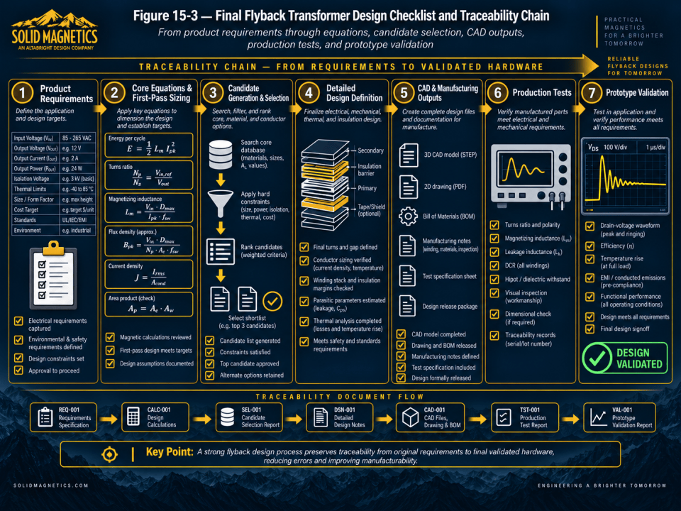
The final traceability chain connects requirements to calculations, selected candidates, detailed design records, CAD and manufacturing documentation, production test results, and prototype validation. Maintaining this relationship makes engineering changes easier to evaluate, improves manufacturing repeatability, and provides a clear record of why the transformer was designed and released the way it was.
Figure 15-3. Final flyback transformer design checklist and traceability chain from product requirements through equations, candidate selection, CAD/manufacturing outputs, production tests, and prototype validation.
21. Conclusion — From Flyback Theory to a Buildable Transformer
Flyback transformer design is often introduced as a small set of equations for turns ratio, magnetizing inductance, and flux density. Those equations are necessary, but a production transformer requires much more: operating-mode analysis, current stress, air-gap design, material selection, conductor engineering, isolation, parasitic control, thermal design, manufacturing controls, and validation.
The purpose of this Ultimate Guide has been to connect those disciplines into one continuous workflow. Each chapter adds another layer of engineering reality until the result is no longer an abstract transformer but a component that can be built, tested, and integrated into a converter.
Automation is especially valuable because the workflow contains many repeated calculations, operating corners, candidate comparisons, tolerance checks, and CAD variables. The engineer remains responsible for requirements, safety context, judgment, and validation, while software can dramatically reduce repetitive effort and improve consistency.
SOLIDMAG ENGINEERING INSIGHT
The Goal Is Not to Automate Engineering Away
The goal is to automate the repetitive parts of engineering so that more time can be spent on architecture, tradeoffs, risk, validation, and innovation.
A well-designed automated magnetic workflow should make engineering decisions more visible and traceable—not less.
Technical References for This Chapter
This chapter synthesizes the equations, design relationships, and workflow developed throughout Chapters 1–14. Final designs should use the applicable controller datasheet, ferrite and bobbin manufacturer data, conductor data, insulation-system approvals, product safety standards, and prototype measurements.
Related SolidMagnetics Resources
Ready to Design a Flyback Transformer?
Move from design theory to an automated magnetic design. Enter the converter requirements and evaluate a coordinated transformer candidate, winding geometry, loss estimates, thermal performance, and CAD output.
← Previous Chapter
Guide Home →
