
Chapter 11 turns the conductor choices from Chapter 10 into a physical winding build. The winding order, insulation barrier, margins, interleaving, start-and-finish locations, auxiliary placement, shields, leads, and pin assignments directly affect safety, leakage inductance, capacitance, EMI, copper loss, regulation, and manufacturability.
← Previous Chapter
Next Chapter →
In This Chapter — Click to Expand
Table of Contents
1. Winding Arrangement Is an Electrical Design Decision
A flyback winding is not simply a collection of turns placed wherever they fit on the bobbin. The order and position of the windings determine how closely the magnetic fields overlap, how much primary-to-secondary capacitance is created, how much leakage inductance remains, and how well the insulation system can be manufactured repeatably.
The winding construction also controls mean turn length, layer count, local electric-field stress, heat distribution, lead routing, and the amount of usable winding window consumed by insulation and margins.
For this reason, winding arrangement should be developed while the electrical and magnetic design is still being iterated—not after the core, turns, and conductors have been frozen.
SOLIDMAG ENGINEERING INSIGHT
Winding Geometry Is Part of the Converter
The transformer winding controls parasitic elements that appear directly in the converter schematic even though they are not intentionally drawn there. Leakage inductance, interwinding capacitance, winding resistance, and common-mode coupling are all consequences of the physical build.
A winding arrangement that is mechanically convenient but electrically poor can erase the benefits of an otherwise excellent magnetic design.
2. Establish Isolation and Safety Requirements Before Winding Order
Before choosing primary-secondary order, interleaving, or margins, define the isolation system required by the end product.
- Working voltage across the isolation barrier
- Required dielectric withstand voltage
- Basic, supplementary, double, or reinforced insulation
- Applicable product safety standard
- Pollution degree
- Material group
- Overvoltage category
- Operating altitude
- Required creepage and clearance
- Bobbin and insulation-system approvals
- Temperature class and lifetime requirements
These requirements determine the minimum physical separation and insulation system between primary-referenced and secondary-referenced conductors. They may also constrain the bobbin, pin layout, wire type, tape system, and winding order.
ENGINEERING CAUTION
Do Not Use Generic Creepage and Clearance Numbers
Required creepage and clearance depend on the end-product standard and operating environment. Use the applicable safety standard and actual working/transient voltages rather than copying a spacing value from another transformer design.
3. Clearance, Creepage, and the Isolation Boundary
Clearance is the shortest distance through air between conductive parts. Creepage is the shortest distance along an insulating surface. The transformer must preserve both across the complete isolation boundary.
Potential weak points include:
- Winding edges
- Start and finish leads
- Lead crossings
- Bobbin pins
- Solder joints
- Core clips and mounting hardware
- Margin tape edges
- Sleeving terminations
- PCB pads and copper underneath the transformer
A thick insulation barrier between the center portions of the primary and secondary does not automatically guarantee adequate creepage at winding edges or leads.
A flyback transformer isolation system extends beyond the insulation placed directly between the windings. Creepage, clearance, bobbin margins, lead routing, pin spacing, and the complete primary-to-secondary physical boundary must all be considered together.

In a conventional radial winding build, the primary winding is typically placed closest to the bobbin and center leg, followed by the required primary-to-secondary insulation system and then the secondary winding farther outward. The insulation barrier establishes the internal isolation boundary, while creepage along insulating surfaces, clearance through air, lead routing, and pin separation maintain isolation throughout the complete transformer assembly.
Figure 11-1. Flyback transformer isolation boundary showing creepage, clearance, primary and secondary zones, bobbin margins, lead routing, and pin separation.
4. Simple Primary–Secondary Winding Arrangement
The simplest isolated construction places the complete primary winding first, applies the required primary-to-secondary insulation barrier, and then places the secondary winding above it.
A typical radial build may be represented as:
| Radial Position from Bobbin | Typical Layer |
|---|---|
| Innermost | Primary winding |
| Next | Primary-to-secondary insulation barrier |
| Outermost | Secondary winding |
Advantages can include straightforward manufacturing, a clearly defined isolation barrier, and simple winding documentation.
Potential disadvantages include greater physical separation between the coupled windings and therefore higher leakage inductance than more interleaved constructions.
SOLIDMAG ENGINEERING INSIGHT
Simple Construction Can Be the Best Construction
Do not add split windings or interleaving automatically. If leakage and regulation are already acceptable, a simpler primary-secondary build may provide lower capacitance, easier safety control, lower manufacturing cost, and better repeatability.
5. Split-Primary Winding Arrangement
A split-primary construction divides the primary into two series-connected winding sections and places the secondary between them.
| Radial Sequence | Function |
|---|---|
| Primary Section 1 | Inner portion of series primary |
| Isolation barrier | Maintains primary-secondary insulation |
| Secondary winding | Main isolated output winding |
| Isolation barrier | Maintains primary-secondary insulation |
| Primary Section 2 | Outer portion of series primary |
The two primary sections must be connected with the correct polarity so that their magnetomotive forces add. The turns are often divided approximately evenly, although integer turns, layer fit, winding width, and parasitic optimization may justify an unequal split.
A split primary can reduce leakage inductance because the secondary is magnetically closer to both portions of the primary.
The tradeoff is usually increased primary-to-secondary interface area, which can increase interwinding capacitance and common-mode coupling.
A split-primary winding divides the primary into two series-connected sections and places the secondary between them. This arrangement can reduce magnetic-field separation between the primary and secondary compared with a simple primary-secondary stack while still maintaining the required insulation barriers.
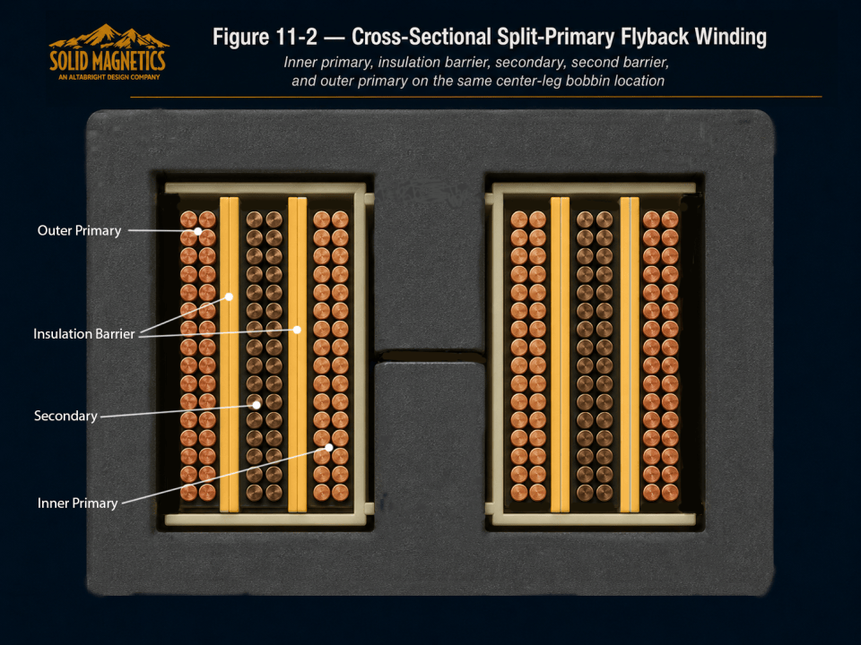
In the cross section shown, the winding build progresses radially from the center leg through the bobbin to the inner primary, first insulation barrier, secondary winding, second insulation barrier, and outer primary. The split-primary arrangement can improve coupling and reduce leakage inductance, but the increased primary-to-secondary interface area may also increase interwinding capacitance. Both effects must therefore be evaluated together in the final transformer design.
Figure 11-2. Cross-sectional split-primary flyback winding showing inner primary, insulation barrier, secondary, second barrier, and outer primary on the same center-leg bobbin location.
6. Interleaving and Sectioned Windings
More aggressive interleaving divides one or both windings into multiple sections to reduce magnetic-field separation between coupled conductors.
Interleaving can:
- Reduce leakage inductance
- Improve coupling
- Reduce some leakage-related voltage overshoot
- Improve cross-regulation in some multi-output designs
It can also:
- Increase primary-to-secondary capacitance
- Increase common-mode EMI coupling
- Create more insulation interfaces
- Increase winding complexity
- Increase assembly time
- Increase risk of phasing or connection errors
ENGINEERING CAUTION
Minimum Leakage Is Not the Only Objective
A design with extremely low leakage can still fail EMC because of excessive interwinding capacitance. Chapter 12 will evaluate leakage and capacitance as a coupled tradeoff.
7. Effective Winding Width, Margins, and Turns per Layer
The usable axial winding width is reduced by margins and manufacturing clearance. A simple first-pass estimate is:
| Variable | Meaning |
|---|---|
| WEFF | Effective winding width available for turns |
| WB | Nominal bobbin winding width |
| ML | Left-side margin or clearance |
| MR | Right-side margin or clearance |
For a round conductor with effective pitch pW, the approximate turns per layer are:
The approximate number of layers is:
This simple geometry is useful for early winding-fit calculations. Real builds must also allow for conductor irregularity, tape thickness, layer transitions, lead exits, and manufacturing tolerance.
SOLIDMAG ENGINEERING INSIGHT
Margins Reduce More Than Window Area
Reducing effective winding width can increase turns per layer pressure, total layer count, mean turn length, leakage inductance, and proximity loss. Safety margins therefore feed directly back into electrical and thermal design.
8. Interwinding Insulation Systems
Primary-to-secondary insulation can be implemented using one or more qualified insulation methods:
- Insulating tape
- Bobbin barriers
- Margin tape
- Sleeving
- Triple-insulated wire
- Molded insulation
- Physical winding separation
- Approved insulation-system combinations
The required material, thickness, number of layers, overlap, and construction depend on the applicable safety requirement.
The insulation must survive winding tension, thermal cycling, soldering, vibration, manufacturing handling, and product life without losing dielectric integrity.
ENGINEERING CAUTION
Insulation Thickness Alone Does Not Define Isolation
Safety approval depends on the complete insulation system, including creepage, clearance, material approvals, winding edges, leads, pins, bobbin geometry, and production controls.
9. Triple-Insulated Wire
Triple-insulated wire can simplify some reinforced-insulation transformer constructions by placing a qualified insulation system directly around the conductor.
Potential benefits include fewer interwinding tape layers and greater winding-layout flexibility.
Important tradeoffs include:
- Larger outside diameter
- Reduced copper fill
- Higher material cost
- Minimum bend radius
- Special stripping and termination procedures
- Approved construction requirements
- Temperature limitations
- Supplier-specific certification constraints
The outside diameter—not only copper diameter—must be used in turns-per-layer and window-fill calculations.
10. Start and Finish Orientation, High-dV/dt Nodes, and Electric-Field Control
The physical start and finish locations of a winding can influence capacitive coupling and common-mode EMI.
A primary terminal connected to a high-dv/dt switching node can capacitively couple noise into adjacent windings. In some constructions, winding orientation can place the highest-dv/dt end closer to or farther from sensitive secondary structures.
The preferred orientation depends on:
- MOSFET and primary switch-node location
- Winding order
- Shielding
- Bobbin geometry
- Common-mode EMI behavior
- Isolation and creepage constraints
Start and finish terminals, winding direction, and polarity should be documented on the transformer drawing rather than left to manufacturing interpretation.
11. Auxiliary Winding Placement
Auxiliary-winding placement depends on what the winding must track and which side of the isolation barrier it belongs to.
A primary-referenced controller-bias winding may be placed with the primary-side construction. An isolated auxiliary output may require full primary-secondary insulation. An auxiliary winding intended to track the main secondary may benefit from stronger magnetic coupling to the secondary.
Evaluate:
- Electrical reference
- Required isolation class
- Desired voltage tracking
- Cross-regulation
- Leakage inductance
- Winding polarity
- Rectifier orientation
- No-load and transient behavior
SOLIDMAG ENGINEERING INSIGHT
Auxiliary Placement Is a Regulation Decision
The number of auxiliary turns establishes only the ideal voltage ratio. Winding placement determines how well that winding tracks the flux and load behavior of the winding it is intended to follow.
12. Electrostatic Shields and Common-Mode Current
An electrostatic shield can be used to redirect or reduce capacitive coupling between primary and secondary structures.
A conductive shield must be designed so it does not form a closed shorted turn around the magnetic flux. A typical foil shield is electrically open at one end and connected to an appropriate reference at one point.
Shielding can affect:
- Primary-to-secondary capacitance
- Common-mode EMI
- Leakage inductance
- Available winding area
- Insulation
- Thermal behavior
- Safety certification
ENGINEERING CAUTION
Never Create a Closed Conductive Turn Around the Core
A closed foil or conductive loop linking the core flux behaves as a shorted secondary winding and can create destructive current and loss. Shield geometry must remain electrically open around the magnetic path.
13. Lead Routing, Pins, Sleeving, and PCB Isolation
The isolation design continues through the winding leads and into the PCB. Lead routing can defeat a carefully designed internal barrier if primary and secondary leads cross or terminate too closely.
Verify:
- Primary and secondary pin grouping
- Lead sleeving
- Lead crossings
- Pin-to-pin creepage
- Solder-joint spacing
- PCB creepage and clearance
- Copper under the transformer
- Core clip or shield connections
- Mechanical strain relief
Where several pins are paralleled for high current, the pin arrangement must still preserve the isolation boundary.
14. Worked Example — Building the Chapter 10 Conductors into a Winding Stack
DESIGN ASSUMPTION
Educational Winding-Layout Example
This example uses illustrative bobbin and insulation dimensions to demonstrate the geometric process. Final safety spacing must come from the applicable end-product standard and actual approved materials.
| Parameter | Illustrative Value |
|---|---|
| Bobbin winding width | 20 mm |
| Left margin | 2.5 mm |
| Right margin | 2.5 mm |
| Effective winding width | 15 mm |
| Primary turns | 32 |
| Secondary turns | 4 |
| Primary conductor effective pitch | 0.75 mm |
| Secondary construction | Two parallel insulated conductors / equivalent high-current construction |
| Preferred arrangement | Split primary |
Step 1 — Calculate Effective Winding Width
Step 2 — Estimate Primary Turns per Layer
A 32-turn primary can therefore be divided into two 16-turn sections, each fitting nominally within one layer under the stated simplified pitch assumption.
Step 3 — Build the Radial Stack
| Radial Position | Illustrative Construction |
|---|---|
| Innermost | Primary Section 1 — 16 turns |
| Next | Primary-to-secondary insulation barrier |
| Next | Secondary — 4 turns / high-current conductor construction |
| Next | Primary-to-secondary insulation barrier |
| Outermost | Primary Section 2 — 16 turns |
Step 4 — Evaluate the Main Tradeoff
The split-primary arrangement can improve coupling relative to a simple primary-secondary stack, but it increases primary-secondary interface area and therefore may increase interwinding capacitance.
The construction must be evaluated in Chapter 12 for:
- Primary-referred leakage inductance
- Primary-to-secondary capacitance
- MOSFET drain overshoot
- Clamp loss
- Common-mode EMI
SOLIDMAG ENGINEERING INSIGHT
A Winding Stack Is a Hypothesis Until Parasitics Are Checked
The worked stack is mechanically plausible and may improve coupling, but the design is not complete until leakage and capacitance are estimated or measured.
Chapter 12 determines whether the proposed physical arrangement produces acceptable parasitic behavior.
The worked winding arrangement converts the calculated turns and conductor requirements into a physical split-primary construction. The 32-turn primary is divided into two 16-turn sections, with the high-current secondary positioned between them and isolated by two primary-to-secondary insulation barriers.

The resulting radial stack places the 16-turn inner primary closest to the center-leg bobbin, followed by the first insulation barrier, the 4-turn high-current secondary, the second insulation barrier, and the 16-turn outer primary. This arrangement can improve coupling and reduce leakage inductance compared with a simple primary-secondary stack, but the larger primary-to-secondary interface area can also increase interwinding capacitance. Both effects should be evaluated in the next stage of the flyback transformer design.
Figure 11-3. Worked split-primary winding stack showing effective winding width, 16-turn inner primary, insulation barrier, 4-turn high-current secondary, second barrier, and 16-turn outer primary.
15. Winding and Isolation Documentation
A production transformer requires a winding specification that can be reproduced without relying on unwritten knowledge. Document:
- Winding order
- Start and finish terminals
- Number of turns
- Wire or conductor type
- Parallel strand count
- Winding direction
- Turns per layer
- Layer count
- Tape material and number of layers
- Margin dimensions
- Interwinding barriers
- Auxiliary winding location
- Shield construction and connection
- Lead routing and sleeving
- Pin assignments
- Core gap
- Core assembly and adhesive
- Required production tests
The transformer drawing should communicate both electrical intent and manufacturing construction.
16. Winding Arrangement and Isolation Checklist
- Isolation classification and applicable safety standard are defined.
- Required creepage and clearance are known.
- Primary and secondary pin groups preserve the isolation boundary.
- Effective winding width includes margins and manufacturing clearance.
- Turns per layer and layer count are practical.
- Winding order is explicitly defined.
- Split or interleaved sections have correct polarity.
- Primary-to-secondary insulation system is documented.
- Triple-insulated wire requirements are documented where used.
- Auxiliary winding reference and placement are defined.
- Electrostatic shields cannot form a closed turn.
- Start/finish orientation is deliberate.
- Lead routing and sleeving maintain isolation.
- The complete winding stack fits within the bobbin.
- Construction will be evaluated for leakage and capacitance in Chapter 12.
17. Design Handoff to Leakage Inductance, Capacitance, and EMI
Chapter 11 has produced a plausible physical winding construction. The next step is to quantify the electrical parasitics created by that construction.
Chapter 12 will evaluate:
- Coupling coefficient
- Primary-referred leakage inductance
- Leakage stored energy
- Drain-voltage overshoot
- Clamp and snubber implications
- Primary-to-secondary capacitance
- Common-mode current
- Interleaving tradeoffs
- Winding placement and EMI
- Measurement methods
SOLIDMAG ENGINEERING INSIGHT
Isolation, Leakage, and Capacitance Must Converge Together
Increasing winding separation can improve isolation and reduce capacitance but usually increases leakage. Interleaving can reduce leakage but increase capacitance.
The final winding design is therefore the construction that satisfies safety while balancing both parasitic elements and their converter consequences.
Technical References for This Chapter
Use the applicable product-safety standard, approved insulation-system documentation, bobbin data, conductor approvals, and transformer-manufacturing requirements for the final isolation construction. This chapter provides engineering structure but does not replace product-specific safety certification.
Related SolidMagnetics Resources
Ready to Design a Flyback Transformer?
Move from design theory to an automated magnetic design. Enter the converter requirements and evaluate a coordinated transformer candidate, winding geometry, loss estimates, thermal performance, and CAD output.
← Previous Chapter
Next Chapter →
